

 *
*

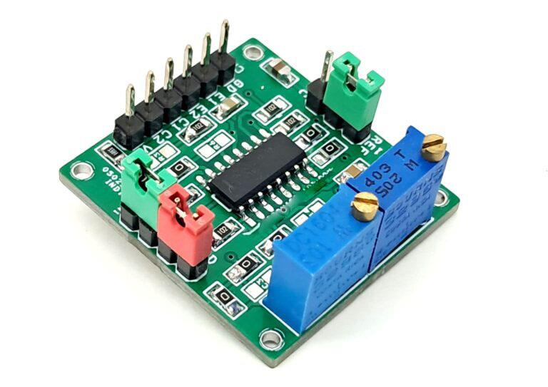
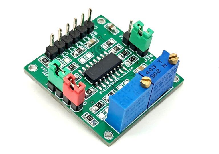
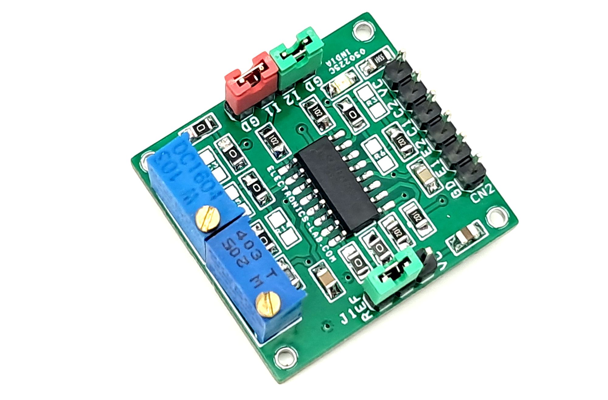
This is a versatile PWM generator module built around the TL494 PWM control chip. The flexible design allows for multiple component configurations to support various applications. Users can customize the module by installing only the components required for their specific application while leaving out unnecessary components.
Features
- Power Supply 7V to 40V DC
- Complete PWM Power-Control Circuitry
- Uncommitted Outputs for 200-mA Sink or Source Current
- Output Control Selects Single-Ended or Push-Pull Operation
- Internal Circuitry Prohibits Double Pulse at Either Output
- Variable Dead Time Provides Control Over Total Range
- Internal Regulator Provides a Stable 5-V REF
- Reference Supply With 5% Tolerance
- Circuit Architecture Allows Easy Synchronization
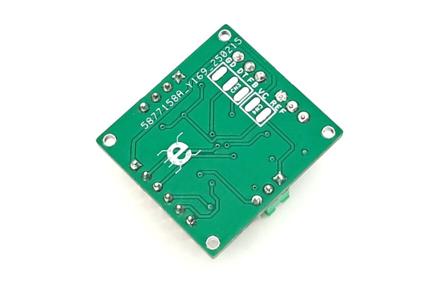
- PCB Dimensions 29.21 x 27.15 mm
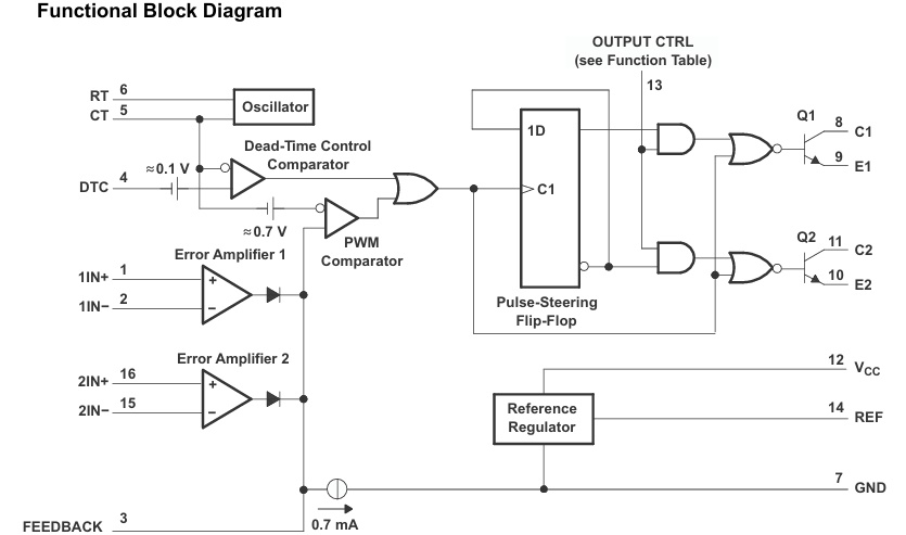
Core Features of TL494
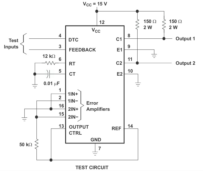
The TL494 integrates all essential PWM control functions into a single chip. Though primarily designed for power supply control, its versatility makes it suitable for various applications. The device includes two error amplifiers, an adjustable on-chip oscillator, a dead-time control (DTC) comparator, a pulse-steering control flip-flop, a precision 5V (±5%) regulator, and output control circuits.
Technical Specifications
- Error amplifiers operate within a common-mode voltage range of -0.3V to VCC – 2V
- Dead-time control comparator features a fixed offset providing approximately 5% dead time
- Oscillator can be bypassed by connecting RT to the reference output and providing a sawtooth input to CT
- Supports synchronous operation in multiple-rail power supplies
- Output configuration flexibility through uncommitted output transistors
- Common-emitter or common-collector output selection via resistor pairs R17+R18 and R12+R13
- Supports both push-pull and single-ended output operation
- Architecture prevents double-pulsing of outputs during push-pull operation
Component Specification
All passive components (resistors and capacitors) used on the board are in 0805 SMD package size.
Sample Application – Adjustable PWM Generator
This module can be configured as an adjustable PWM generator with the following features:
- Duty cycle adjustment range: 5% to 95% (controlled via multiturn trimmer potentiometer PR1)
- Frequency adjustment range: 100Hz to 50kHz (controlled via multiturn trimmer potentiometer PR2)
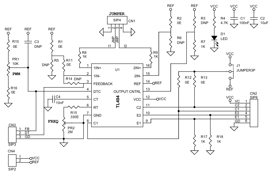
For implementation, please refer to the schematic diagram and install only the components specified for this configuration.
Connector and Component Details
CN1: Jumper Configuration
-
Use jumper closures (shunts) to short:
- Pins 1 and 2
- Pins 3 and 4
D1: LED Indicator
- Functions as power status indicator
J1: Output Voltage Selection Jumper
- Short with Ref: Provides 5V PWM output
- Short with VCC: Provides high voltage PWM output
PR1: PWM Duty Cycle Adjustment
- Trimmer potentiometer for adjusting duty cycle
- Adjustment range: approximately 5% to 95%
PR2: Frequency Adjustment
- Trimmer potentiometer for frequency control
- Adjustment range: 100Hz to 50kHz
CN2: Main Connection Terminal (6-pin)
- Pin 1: VCC input (7V to 40V)
- Pin 2: Collector 2 output
- Pin 3: Collector 1 output
- Pin 4: Emitter 2 output (PWM Output)
- Pin 5: Emitter 1 output (PWM Output)
- Pin 6: Ground (GND)
CN3 and CN4: Not in use
Schematic
Parts List
Connections

Application Diagram
Block Diagram
Gerber View
Photos


