STM32-Quadcopter Drone Design Open Source
 04 Feb 2026 10:10:01 GMT
Tyson From www.hycxpcba.com
04 Feb 2026 10:10:01 GMT
Tyson From www.hycxpcba.com
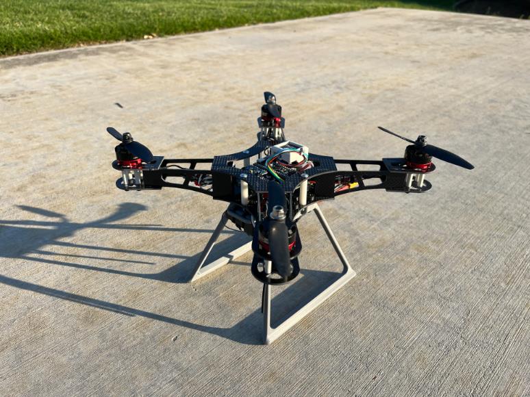

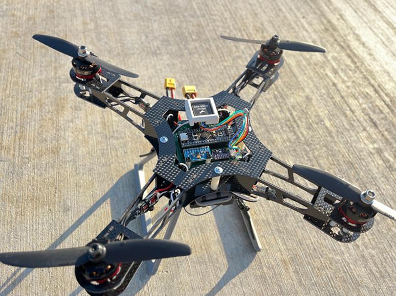
This is a quadcopter design based on the STM32F411CEU Blackpill flight controller. The flight controller is compatible with INAV 6.0 firmware.
The flight controller uses an MPU6500 for inertial measurements and a BMP280 for altitude sensing, and also supports an optional GPS and magnetometer module.
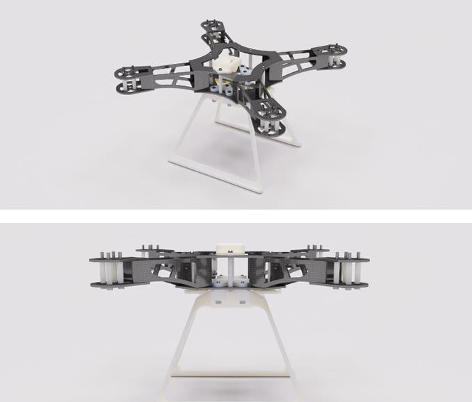
The frame is composed mostly of 2D parts cut from carbon-fiber sheets. Alternatively,
you can 3D-print parts in carbon-fiber-reinforced filaments (PET-CF, PAHT-CF, PA6-CF, PPS-CF), with less-critical components in ABS.
1.I-M-Robotics-Lab/STM32-Quadcopter — Contains firmware targets, CAD models, PCB/schematics.
2.MakerWorld Page: 3D Printable Frame Models — Ready-to-print and CNC-cut parts with print profiles.
3.Community Discord: I-M Robotics Lab Server — Ask questions, share builds, and collaborate with contributors.

1.STM32-Quadcopter — Contains firmware targets, CAD models, PCB/schematics.:
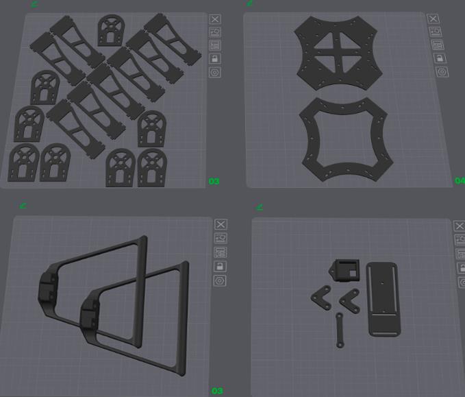
Frame
Use the assembled CAD model in the 3.Models/ folder as a reference to build.:
CF Components anABS Components :
Mechanical Components BOM
| Item Name | Qty |
|---|---|
| M3 Hex Nut | 19 |
| M3 x 12mm Button Head Bolt | 2 |
| M3 x 20mm Button Head Bolt | 7 |
| M3 x 20mm Socket Head Bolt | 6 |
| M3 x 30mm Socket Head Bolt | 16 |
| M3 x 35mm Button Head Bolt | 3 |
| M3 x 40mm Button Head Bolt | 1 |
| Nylon Spacer 3-5-11.2 | 8 |
| Nylon Spacer 3-5-20 | 16 |
| Nylon Spacer 3-5-30 | 4 |
| Nylon Spacer 3-5-5 | 2 |
Electronics Structure:
1. Electronics/
  ├── Extra/
  │   ├── *.step
  │   └── ...
  ├── Hardware-backups/
  │   └── ...
  ├── Production/           ← Gerber output for fabrication
  │   ├── Hardware-B_Cu.gbl
  │   └── ...
  ├── Hardware.kicad_pcb    ← KiCAD PCB file
  ├── Hardware.kicad_sch    ← KiCAD Schematics file
  ├── Hardware.kicad_pro    ← KiCAD project
  ├── JLCPCB.kicad_dru      ← Rules for JLCPCB manufacturing
  ├── Production.zip        ← Gerber
  └── Schematics.pdf        ← Schematics
| Component | Qty |
|---|---|
| RS2205 BLDC Motor | 4 |
| BLHeli_S 20A ESC | 4 |
| 5030R Propeller | 2 |
| STM32F411CEU6 “Blackpill” | 1 |
| MPU6500 / MPU9250 Module | 1 |
| BMP280 Module | 1 |
| 330 µF @ 50 V Capacitor | 1 |
| FS-iA6B Receiver | 1 |
| FS-iA6B Transmitter | 1 |
| Ovonic 1500 mAh 120C 3s Battery | 1 |
| XT60 Connector | 1 |
Sample Diagram:
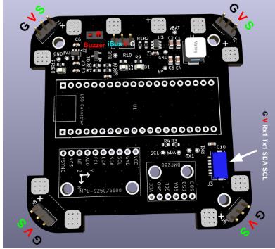
GPS (UART1) Wiring
Ensure connectors are wired correctly according to the pinout. Note that RX should connect to TX: RX1 → GPS TX, TX1 → GPS RX.
Capacitor for Spike Filtering
One or more bulk electrolytic capacitor is recommended to protect against voltage spikes. Use an electrolytic capacitor such as 330 µF @ 50 V
and place it between VBAT and GND near the input. For extra protection, a TVS diode clampeing at ~12 V is ideal.
Firmware
Build
The firmware used is INAV v6.0.0 (github link). This project does not support INAV v7+ currently due to USB issue.
If one wants to modify the target file or other configurations of the firmware, they must rebuild the binary. Follow this guide to build:
Prerequisites
CMake ≥ 3.15
Ninja
gcc-arm-none-eabi toolchain
Clone INAV
git clone https://github.com/iNavFlight/inav.git
cd inav
git checkout 6.0
Add Target
Copy the entire 2.Firmware/GYW_BLACKPILL_F411 folder into the local INAV repository under src/main/target/ so that it ends up as:
inav/
└── src/
└── main/
└── target/
├── GYW_BLACKPILL_F411/
└── ...
Patch Code
INAV 6.0 doesn’t support a 25 MHz HSE clock by default, so if your board (like the Blackpill F411) uses a 25 MHz crystal, you must update the PLL setup in src/main/target/system_stm32f4xx.c as follows:
In system_stm32f4xx.c, locate the PLL setup region and modify it as follows:
#if defined(STM32F40_41xxx) || defined(STM32F427_437xx) || defined(STM32F429_439xx) || defined(STM32F401xx) || defined(STM32F469_479xx) || defined(STM32F446xx) || defined(STM32F410xx) || defined(STM32F411xE)
+ #if HSE_VALUE == 25000000
+ #define PLL_M 25
+ #elif HSE_VALUE == 24000000
- #if HSE_VALUE == 24000000
#define PLL_M 24
#elif HSE_VALUE == 16000000
#define PLL_M 16
#elif HSE_VALUE == 8000000
#define PLL_M 8
#else
#error Invalid HSE_VALUE
#endif
#else
#error Undefined CPU
#endif
Build
Ensure that you have installed all dependencies. Inside the inav root repository execute:
mkdir -p build && cd build
cmake .. -G Ninja \
-DBOARD=GYW_BLACKPILL_F411 \
-DCMAKE_TOOLCHAIN_FILE=../tools/cmake/toolchain-arm-none-eabi.cmake
ninja
The firmware binary should be at build/inav_6.0.0_GYW_BLACKPILL_F411.hex.
Flash
First, download the INAV Configurator v6.0.0 from this link. Once installed, launch INAV Configurator and connect to the Blackpill via USB.
Cut the red wire in the USB cable to prevent it from powering the Blackpill. Instead, power the flight controller using an external 3S battery.
MPU9250 Issue
If you are using a MPU9250 module, you may encounter the problem that INAV does not recognize the accelerometer.
This is due to many boards labeled MPU9250 actually house only an MPU6500 (omitting or substituting the magnetometer).
Since drones often use an external magnetometer, this usually isn’t critical if your accelerometer and gyro (MPU6500) work.
To identify your chip, read the WHO_AM_I register (0x75) via I²C (use an Arduino or something similar to do this part). Example Arduino code:
#include <Wire.h>
const uint8_t MPU_ADDR = 0x68; // I²C address
const uint8_t WHO_AM_I_REG = 0x75;
void setup() {
Serial.begin(115200);
Wire.begin();
delay(100);
Wire.beginTransmission(MPU_ADDR);
Wire.write(WHO_AM_I_REG);
if (Wire.endTransmission(false) != 0) {
Serial.println(F("no device found")); while (1);
}
Wire.requestFrom(MPU_ADDR, (uint8_t)1);
if (Wire.available()) {
uint8_t id = Wire.read();
Serial.print(F("WHO_AM_I = 0x"));
Serial.println(id, HEX);
} else {
Serial.println(F("no data returned"));
}
}
If it prints 0x71, it’s MPU6500; 0x73 indicates MPU9250.
The current binary file and target is configured for MPU6500. To use MPU9250, comment out the block for MPU6500 and uncomment the MPU9250 block in the target file. Rebuild the binary and flash. It looks like this:
#define USE_IMU_MPU9250
#define IMU_MPU9250_ALIGN CW0_DEG
#define MPU9250_CS_PIN PB12
#define MPU9250_SPI_BUS BUS_SPI2
2. 3D Printable Frame Models — Ready-to-print and CNC-cut parts with print profiles.
Download 3D file:https://makerworld.com/en/models/1695470-quadcopter-3d-printable-stm32-mcu#profileId-1797658
-
06 Mar 2026 14:08:44 GMT
What is Heavy Copper PCB
-
04 Mar 2026 10:15:22 GMT
How Dose AOI Enhances Solder Paste Inspection For PCB